Search This Blog

Sunday 27 November 2016

ADC -- Jupiter Modular Receiver

SECTION 8  — ADC


Click for the Master Index to this project


Radio astronomy requires a receiver output data stream to make sense of what you receive. Computer programs may convert the data into graphs, FFTs, spectrograms, or pool it with other data in hopes of digging the signal out of the noise. At this point, I'm happy with a simple X-Y graph and hopefully my methods will evolve over time.

After much reading + thinking and some hardware failures, I settled on a commercial product to stream data into my computer via a USB cable and then use homebrew + commercial programs to massage my data.


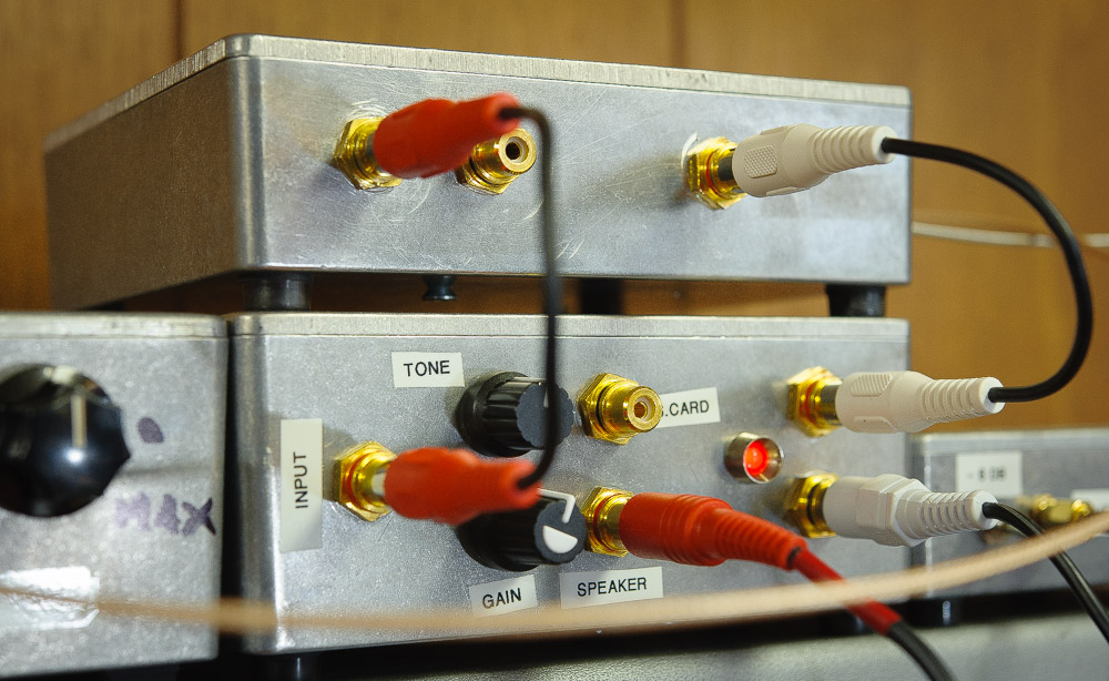
Above — A 4 analog channel, 15-bit ADC from Electronic Energy Control, in Mildford Center, Ohio, USA. The product is called the ADC-4U15. Click for the EECI Website
EECI provides amazing customer service plus innovative solutions for data streaming. 

The on-board USB-to-Serial Bridge Controller = a Prolific PL-2303 HX.  Click for Prolific's web site. The PL-2303 contains an on-chip clock, so I put the board in a RF shielded container fashioned with 2-sided copper clad board. Unlike some ADCs sold today, the PL-2303's drivers were MS Windows certified; they installed and worked on my first try.


Above — I carved out a hole for the USB, Type B connector with a hammer and chisel before soldering it to the rest of the enclosure. My USB cable has ferrite beads on both ends. On the RCA input port, I placed a 100n bypass capacitor.

I'm currently only using Channel 1 of the ADC, so the other 3 inputs are shorted to ground.

Data Streaming and Code  

To run the ADC--4U15,  you start a supplied application that establishes communication to the ADC and an output number between 0 and 32767 ( 15 - bits) appears for each of the 4 data channels.


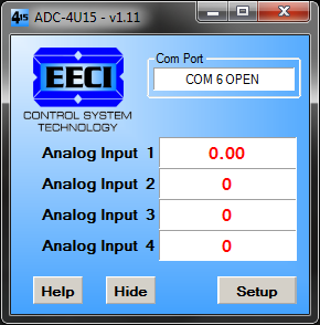
Above — The ADC-4U15 controller application. Once I plug the ADC to its USB port and start this application, I normally hide it -- and it runs in the background.


Above — setup dialog box for the  ADC-4U15 controller application. Once you set the com port, sample rate and maximum voltage of your data channel(s), it's set and forget. This application provides a data logger output, but you don't have to use it. EECI provides some source code to get you going in both C# and VB. The ADC-4U15 application is a combination user interface and USB driver -- you read the 4 digital channels from a Windows memory label

In Microsoft Visual Studio ( free version) I followed Bert from EECIs instructions and created an application that read the Windows memory map and it compiled without errors!


Then it's up to you to add code to convert the 2 byte pairs of each channel into a 16 bit integer -- and then further, to convert it to some usable unit to graph. Of course, you'll need to write code to write to file -- or graph within your application. I chose the former for now.

I kept my units as DC volts since this allowed me to test and calibrate my receiver system to ensure my code was working. At some point when I get my noise figure system going, I'll plot the Y axis in degrees Kelvin.

Since my maximum input reference voltage = 2.05v, to convert a 15 bit full scale integer into 2.05V full scale float, the code goes:  inputVolts[i] = 2.05f * ((float)inputInt[i]) / 0x8000;

Then, code was added to write the data to a CSV file.

Here's my meat and potatoes source code file:

using System;
using System.Collections.Generic;
using System.ComponentModel;
using System.Data;
using System.Drawing;
using System.Linq;
using System.Text;
using System.Threading.Tasks;
using System.Windows.Forms;
using System.IO;
using System.IO.MemoryMappedFiles;

namespace WindowsFormsApplication1
{
    public partial class Form1 : Form
    {
        Byte[] inputByte = new byte[8];     //create byte array
        Int16[] inputInt = new Int16[4];
        float[] inputVolts = new float[4];
        Label[] MyLabelArray = new Label[4];
        StreamWriter csvWriter;
        DateTime startTime;

        public Form1()
        {
            InitializeComponent();
        }

        private void Form1_Load(object sender, EventArgs e)
        {
            CreateLabellArray();

            string csvFilename = string.Format(".\\{0}.csv", DateTime.Now.ToString("yyyy-MM-dd_HH-mm-ss"));
            string csvPath = Path.GetFullPath( Path.Combine(Environment.GetFolderPath(Environment.SpecialFolder.MyDocuments),csvFilename));
            csvWriter = new StreamWriter(csvPath, false, Encoding.ASCII);
            startTime = DateTime.UtcNow;

            csvWriter.WriteLine(
                "UTC Internet format"
                + ", " + "UTC Excel format"
                + ", " + "Local Text format"
                + ", " + "Local Excel format"
                + ", " + "Elapsed seconds"
                + ", " + "Data");

            // update the readings every 200ms
            timer1.Interval = 200;
            timer1.Enabled = true;
        }

        private void Form1_FormClosing(object sender, FormClosingEventArgs e)
        {
            csvWriter.Close();
        }

        private void timer1_Tick(object sender, EventArgs e)
        {
            string csvLine = ReadInputMemoryMap();
            DateTime currentTime = DateTime.UtcNow;
            TimeSpan elapsedTime = (currentTime - startTime);
            TimeSpan excelTime = currentTime - DateTime.Parse("1900-01-01 00:00:00").ToUniversalTime();

            csvWriter.WriteLine(
                currentTime.ToString("yyyy'-'MM'-'dd'T'HH':'mm':'ss'.'fff'Z'") // UTC Internet format
                + ", " + (excelTime.TotalDays - TimeZone.CurrentTimeZone.GetUtcOffset(currentTime.ToLocalTime()).TotalDays + 2).ToString("0.000000") // UTC Excel format
                + ", " + currentTime.ToLocalTime().ToString("yyyy'-'MM'-'dd HH':'mm':'ss'.'fff") // Local Text format
                + ", " + (excelTime.TotalDays + 2).ToString("0.000000") // Local Excel format
                + ", " + elapsedTime.TotalSeconds.ToString("0.000") // Elapsed seconds
                + ", " + csvLine); // data value

            for (int i = 0; i < 4; i++)
            {
                MyLabelArray[i].Text = inputVolts[i].ToString("0.0####");
            }

            labelTimeStamp.Text = elapsedTime.ToString(@"d\.hh\:mm\:ss");
        }

        private string ReadInputMemoryMap()
        {
            try
            {
                MemoryMappedFile file = MemoryMappedFile.OpenExisting("EECI_ADC4U15_OUT");
                MemoryMappedViewAccessor reader = file.CreateViewAccessor();
                for (int i = 0; i < 8; i++)
                {
                    inputByte[i] = reader.ReadByte(i);
                }

                for(int i=0; i<4; i++)
                {
                    // convert 2 byte pairs into 16 bit integer
                    inputInt[i] = (Int16)((((UInt16)inputByte[i]) << 8) | ((UInt16)inputByte[i + 4]));

                    // convert 15 bit full scale integer into 2.05V full scale float
                    inputVolts[i] = 2.05f * ((float)inputInt[i]) / 0x8000;
                }
            }
            catch (Exception ex)
            {
                labelChannel1.Text = ex.Message;
            }

            return string.Format("{0:0.0####}", inputVolts[0]);
        }

        private void CreateLabellArray()
        {
            MyLabelArray[0] = labelChannel1;
            MyLabelArray[1] = labelChannel2;
            MyLabelArray[2] = labelChannel3;
            MyLabelArray[3] = labelChannel4;
        }
    }
}

The application looks like this currently.


Above — Channel 1 is expressed as a DC voltage. All other channels are shorted to ground and read 0. Once the app starts up, elapsed time gets displayed. The only purpose of this app is to read the data from memory, massage the data bytes into something usable, and write that data to a CSV file in a format that meets my requirements. The file name = the current timestamp.csv. This allows me to keep track of the CSV files by a unique namesake.


Above —The 6 column CSV file allows me to graph in UTC or local time. Microsoft Excel seems to suffer some time stamp issues, so the source code was adjusted to provide an accurate output for my location.


Above — a test plot of my Jupiter receiver during the early evening when my local noise is louder than after midnight. I've calibrated my receiver's DC output voltage against known amplitude input signals from -121 to - 47 dBm and wrote some of them on the graph in red.

My graphing process will likely change over time. It's nice to finally have data to work with.


Sunday 13 November 2016

Log Amplifer -- Jupiter Modular Receiver

SECTION 7  — Log Amplifier


Click for the Master Index to this project


After many experiments and 4 versions, I settled on my simplest design.


The AD8307 splendidly responds to input signals from DC to ~ 500 MHz, so it can work well for a DC or ZIF receiver. However, any pulsing noise on its positive rail, or at the input may get converted to a DC output and wreck your log response and accuracy. Not to mention -- any detected RF will likewise wreck your day.

Above all, I learned it's essential to put it in a metal box and filter the DC rail and input heavily. My analog meter registers a receiver input signal from - 121 dBm ( S1 ) to  - 43 dBm ( S9 + 30 dB )  Note: measures made with a low noise + distortion continuous wave available power connected to the 50 Ω port of the filter / preamplifer with the receiver tuned to generate a 1 KHz AF tone at the receiver AF output.


Above — Final schematic of my Jovian logarithmic amplifier module.

DC Filtration 

I'll first discuss the DC filtration. In past log amps featuring the AD8307, I ran battery power to eliminate any noise on the DC rail. In other versions, I added active ripple filters and for this project compared the results to just using big capacitors to filter the AF ripple. I measured no difference and opted for the 470 + 1000 + 470 µF shown. Further, careful RF filtration delivers reasonable attenuation of RF signals from HF to UHF.


Above — Assessing my wide band RF filtration with a tracking generator + spectrum analyzer. My final network plied a 10 Ω resistor instead of the first 22 Ω resistor as shown above. The reasonable Qul of the1 µH Coilcraft choke plus the 1n caps gives the added attenuation past 40 MHz.  When combining RF capacitors in parallel with low Q Audio Frequency capacitors, no high impedance peaks occur, so it's OK to do this.

Recall that when we combine 2 RF caps in parallel , the inductance of 1 capacitor resonates with the capacitance of the other to form a parallel resonance — leading to a high impedance — that wrecks RF bypass at a specific frequency, although this peak will also exhibit skirts like any band-pass filter. Hence, I've placed either a resistor, or a choke in between the  shunt 1n or 100n RF capacitors.

Input Signal Filtration

My inspiration came from Gary, NA6O ( ex-WB9JPS ) who penned An Accurate S-Meter for Direct Conversion Receivers for QST, February 2008. I recommend his article as a gold-standard reference on this topic. With Gary's permission, I copied his fast attack, slow delay post AD8307 detector circuitry, and the 5 volt supply rail-rail op-amp scheme. Further, Gary nailed the problems ailing the AD8307 at AF with particular insight.

I ended up making 4 circuits and settled on the 1 presented above. This, an experimenters circuit, and likely requires your own nuance. Based on my AD8307 projects, much discussion and emails over the years, accurate log amps may prove thorny and difficult for some builders.

Gary found common-mode noise afflicted his design when receiving small amplitude signals.
He opted for a front-end differential amplifier to reduce this noise while providing adjustable gain to optimize the  AD8307 input amplitude to any direct conversion receiver with known gain to get the best possible dynamic range. I found his conclusion about needing variable gain true plus invaluable. Gain adjustment can be done in the receiver, or the log module; or both.

Further, employing a low noise, rail-to-rail op-amp proved vital.

Let's quickly review common mode noise in differential op-amps since sometimes when I discuss this, the other builder's eyes glaze over.  Differential amps done right reject common mode noise. In differential op-amps, the inverting [-] and non-inverting inputs [+] are driven 180 degrees out of phase. Since unwanted noise or hum appears in-phase on each input ( common mode ), this noise/hum gets rejected and does not appear at the op-amp output. Of course, you need to 1% match the input circuit capacitors and resistors to yield exemplary common mode suppression in an op-amp filter.

In my lab, with a differential amp/filter I obtained good results, but still, my AD8307 lacked sensitivity to measure signals when I applied < -110 dBm to the front end of my single-signal receiver.  For my particular receiver, I found that brute-force R-C filters worked better.

Simple R-C filters get a bad rap; likely because for a first order filter the roll off is only 6 dB per octave and we get so much better with our popular active filter designs.

Let's trace the input of my circuit.

A 680 pF cap connected to the front panel jack filters VHF signals -- especially around the FM broadcast band. From there a 68 Ω resistor plus a 3.3 µF provides a 3 dB down low-pass response @ ~ 709 KHz.  A secondary filter gets formed with the 68 Ω resistor plus shunt 0.1 µF capacitor to filter any HF or LF signals getting into the input.

The 0.33 µF series cap provides some hum immunity into the op-amp unity-gain buffer. An identical 68 Ω R ( labelled RF in the schematic ) plus a 3.3 µF polyester low-pass filters the buffer's output. If your receiver output looks pretty noisy, you may increase RF to as high as 200 Ω to drop that filter's 3 dB cutoff point. Brute force indeed. Set the buffer input and output R-C filter values to what you require.

The two 709 KHz filters attenuate receiver AF wide band noise above 1 KHz that reduced the sensitivity of my log module to measure very low-level signals. With appropriate adjustment of  my receiver output level pot and the meter's zero and calibration knobs, my analog meter reads 0 or nearly zero when the  antenna ( or signal generator ) gets removed and replaced with a 50 Ω resistor terminator. Essentially, the log module nulls the receiver + AD8307 noise with no antenna input signal.

With the analog meter calibrated with a signal generator, and the zero and calibration pots adjusted correctly, I can measure down to -121 dBm or S1. With a voltmeter, I measured signals down around -130 dBm before getting clobbered by the receiver noise floor. Since my
receiver monitors low-level Gaussian noise for radio astronomy, I wanted the meter sensitivity focused towards the low end.


Calibrating my analog S - meter proved easy. I set a calibrated signal generator to 20.190 MHz and tuned the receiver for a 1 KHz AF output signal.  I injected - 73 dBm or S9 and adjusted the meter cal pot to go about 60% of my particular panel meter. Then I decreased power by 6 dBm to find S8 and so on.  When satisfied, I had the range correct. I marked my meter with a black marker for S1- S9 -- and then S9 + 10 dB ( -63 dBm) , S9 + 20 dB and then S9 plus 30 dB. I tested the meter by inserting in-line 6 and/or 10 dB attenuators and so forth. It check out and my meter marks account for any non linearity in the AD8307 circuit.

This gives you a calibrated measurement receiver. I love the S-meter -- and Gary's fast-attack, slow delay detector further boosts the experience. With it, no AD8307 output DC low-pass circuitry is required ( see the datasheet ).

The other output goes to a panel jack for a connection to the an ADC for data acquisition. The 2K7 shunted pot will help calibrate the noise power output on a graph.


Above — First "real world" test with analog meter before I painted its face white and then after, marked the S units with a felt marker in a calibration set up. When I close the -6 dB switch on my preamplifier - filter module, the meter drops by 1 S-unit.  I'm happy!

I've attached 2 of my discarded circuits for experimental fodder.


Click for Module 8, the ADC
Click to return to the main index for this project


Friday 4 November 2016

Zero - IF Jupiter Receiver

SECTION 5  —  Zero - IF Jupiter Receiver Module


Click for the Master Index to this project


In November, amidst other lazy Fall activities, I shed my sloth and torpor and built a zero IF, [ ZIF ] or AF phasing direct conversion receiver module for my Jovian pursuits.

After re-reading Chapter 9 of Experimental Method in RF Design (now out of print), a sketch arose and I ran to the bench to make some sparks. I closely followed much of the circuitry designed by Chapter 9 author Rick, KK7B and also incorporated stuff I've learned from Wes, W7ZOI.


Above — First real-world test of the new (unlabelled) receiver in my modular radio astronomy system. 1 less noise side band to deal with makes me happy.

[1]  Input filter, mixer/amps and AF phase shift networks


Above — Schematic Part 1 shows the design from the RF input to the outputs of the I and Q channel arm all-pass networks.

I opted to in-phase split the RF signal with the popular, broadband, 3 dB hybrid splitter because it's simple and worked well in past adventures.


Above — A GPLA simulation of the input filter's S21 ( gain ) & S11 ( match into 50 Ω @ the input ). The filter will match a 50 Ω antenna with >= 20 dB return loss from 20.56 to 22 MHz. My target = 20.1- 20.3 MHz, but this = close enough and importantly, plys standard value capacitors. It's important to place a filter after the MMIC preamplifier shown in Section 3.


Above — A sweep of the input filter + 3 dB hybrid splitter after I affixed 2 temporary SMA RF connectors and connected a 51 Ω shunt resistor across the unused output port.  The measure is what really matters in RF design ! After a little tweaking of the inductors by spreading or squishing the windings,  I tweaked the stage's attenuation to 3.22 dB; showing my match and gain at ~20.1 MHz look great.

I wound the coils on a T37-6 and a T44-6 toroid with # 26 gauge wire.

Does omission of a diplexer and just going with a 50 Ω high-pass shunt network + an RFC seem reckless? Perhaps, just frugal.  I stuck with the post mixer AF common base preamp popularized by Roy Lewallen, W7EL and promoted by Rick, Wes and others.


Above — Emitter current on my common base post-mixer AF amplifiers.  26/IE = 50 Ω. I felt jubilant I obtained this with 5% resistors. I matched my 2N4401 transistors. From a DC and AC perspective, each channel resembles the other 1. The 12K collector resistor establishes a
collector DC voltage of 5.95v -- this provides about 1/2 VCC virtual ground bias for the op-amp chain that follows each common base amp.

The final DC output voltages --  and AC test signal voltages ( when I injected an AC test signal to the input of each arm ) were within 2% of each other for the 2 arms.  In a ZIF receiver, we want such parity to glean optimal opposite side band suppression. Apart from phase, the I and Q channels should look like each other when viewing with instruments and your physical layout.

The op-amps U1-U4 follow Rick, KK7B's designs. I chose Rick's all-pass network R and C values for 2 reasons. [1]  Since 1995, this design enjoys constant replication and proof of function via measurement by many builders [2] I collected these 1% metal film resistor values and had them on hand.  Our best circuits are always built using whatever parts we've got on hand.

These network values offer the potential for 60 dB opposite side band suppression from 270 - 3600 Hertz. As it turned out, I did OK --- at a 1 KHz offset I measured upper side band suppression at 55 dB!  My best effort to date.

I've designed all-pass filters, but lack the 1% resistors to build them right now.
Click for my blog page covering 90 degree phase shifts.

[2]  I and Q channel summer, AF filter/amplifiers and AF splitter


Above — Schematic Part 2.

A 1K trimmer allows you to set whatever ratio of the I or Q channel needed to optimize side band suppression. A 470 Ω AF gain trimmer pot allows the receiver gain to vary from ~ 44 - 61 dB. I normally choose around 50- 54 dB gain and then make up the additional needed AF gain with the AF power amp -- or gain control circuitry in the log amplifier system.

1 op-amp virtual ground establishes 1/2 VCC on all the op-amp + pins. In my first Jupiter receiver, I chose 6 poles of low-pass filtration with a 3 KHz cut-off. In this design, I opted for 4 poles with a 1 KHz 3dB cut-off. Note the filter response = Gaussian - 12 dB. The meandering G-12 dB group delay sounds the best to my ears -- and never rings. I learned this from Wes. Choose a lower cutoff frequency, less poles and make it a Gaussian response for great sound.  I also do this for crystal ladder filters. We're listening to galactic noise and not competing in the CW sweepstakes after all.

The signal gets bisected by U7. 1 signal goes to the AF amp module, the other to the log amp for output into an S-meter, plus an ADC.


Above — The output of both AF line outputs @ ~ 802 Hz offset with -73 dB available RF power at the receiver input during some testing. 1 bench cable was long, the other short and this resulted in a slight phase shift!

[3]  Quadrature hybrid and photos


Above — The Fisher, twisted wire quadrature hybrid employed inside this receiver to drive the local oscillator ports of the 2 mixers 90 degrees apart.  Equal length RG-174 coax line connect the quadrature to the mixer LO ports, LI and LQ.


Above — Serendipity. I bench tested the quadrature hybrid from 20.1 to 20.3 MHz and the phase shift was exactly 90 degrees. The amplitude difference gets cancelled with the balance trimmer in schematic Part 2.


Above — Full on bench mode. Temporary RF and BNC connectors allow situ testing. With extensive test as-you-go construction, we usually suffer no surprises when placing your completed work in an enclosure. Every op-amp was tested after soldering during the build up -- entire stages were swapped in and out during this build to learn what worked best.


Above — Device in test mode. The Q original mixer was blown and got replaced with 1 I bought in ~1994 from the late Doug DeMaw. I boosted the side band suppression with the balance trimmer after originally getting 53.4 dB and writing in on the Cu+ clad board.


Above —Boxed up.


Above — Testing the module with some other Jovian modules. More to come.

Click for Module 6, the AF amplifier
Click to return to the main index for this project