Salutations!
Minor update June 27, 2022. I added a new working link to Ken Kuhn's spreadsheet, removed the link to the now defunct R2Pro / KK7B Designs Yahoo group, plus edited a few words.
After much thought, I'll focus my further receiver efforts on analog domain phasing receiver design and construction. While great tools, superhet receivers lost their luster for me. Plus, I'll no longer have to deal with birdies, crystal filters, RF mixer products and the IF image.
Quadrature detectors with digital signal processing don't excite me either, however, that may change over time.
For over 40 years I've listened to detected RF through a speaker — enjoying mostly hi fidelity audio. In 2015, I find no reason to change my preferred listening practices. To that end, direct conversion, or zero-IF ( ZIF ) receivers deliver a sonic impact that I don't seem to get with my superhets. Further, digital processing may be applied along the ZIF receiver chain as I eventually modernize my analog dominant, primitive, hobby radio experiments.
Good DC receiver design poses many challenges; especially when you apply phase shifting techniques to suppress the unwanted side band by > 30 dB. Effectively reducing analog gain and/or phase imbalances between the translated I and Q baseband signals without relying on digital signal processing proves no small task. Unrelated issues such as DC offset due to local oscillator leakage also lurk.
How do we obtain a precise, wide band 90 degree phase shift at RF — and also at AF? Presented are some of my first experiments at making 90º analog phase shifts from AF to UHF.
As a 90 degree phase shift newbie, reading the material written by Rick, KK7B published in EMRFD Chapter 9 formed my inaugural task [ Reference #1 ]. Since older cell phones and many other receivers apply ZIF I-Q techniques, we may also find numerous online resources to read.
[1] RF Quadrature Hybrid
I started with the classic 7 MHz "Fisher" quadrature hybrid [ Reference # 2 ] also presented in EMRFD Chapter 9.

Above — We've seen this 3 dB quadrature hybrid schematic in many ARRL articles for 7 MHz.

Above — I quickly built the above 3 dB hybrid with no special attention towards matching the 2 capacitors, or even building a precise layout. I wanted to measure it as a 'typical' build that a beginner might ply. We're so use to Y/T scope graphics that this lovely, round, Lissajous curve from an X-Y plot jumps out at you. This 7 MHz twisted wire 3 dB hybrid coupler works like a charm.

Above — Some Y/T DSO analysis. I measured the insertion loss @ 3.02 dB at Fc. To classify the bandwidth I adopted what I saw on a few datasheets: +/- 10% of the center frequency. I determined my Fc @ 7.060 MHz and felt surprised with its performance.
Like what I've read in the literature, signal amplitude varies much more than phase between the 2 ports as you move up and down in frequency. It's 1 thing to read information — and something entirely different to see it happening before you eyes during real bench experiments.
This simple quadrature will work for the whole 7 MHz Ham band in many phasing receivers.
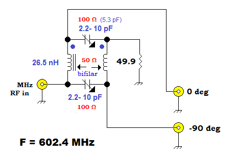
Above — I wanted to see how far up I could take the twisted wire quadrature in frequency. I
- Twisted 2 wires together.
- Smashed up a T30-12 toroid inside a plastic sandwich bag with a hammer.
- Made a slurry of glue + Fe material and dabbed it on the center of the twisted wire.
- Measured the L at 26.5 nH and calculated that XL = 50 Ω @ 602.4 MHz.
- Crudely built a tiny 3 dB hybrid with trimmer capacitors to get the needed XC of 100 Ω.

Above — DSO analysis showed that it worked! Some brief experiments seemed to indicate that a reasonable bandwidth might be possible if careful UHF breadboard practices were applied. I chose Fe material from the T30-12 since it had the lowest permeability of any toroid in my collection. Perhaps, my next experiment should involve no ferrous material?
Commercial 90 º splitter / combiners are available for multiple frequencies. Click for 1 example.
Branch line UHF Quadrature Hybrid
I wanted to make 3 dB quadrature hybrid for ~435 - 438 MHz: the ~ 70 cm amateur satellite band.
Commonly, builders insert a 90º λ/4 transmission line delay to make a power divider. Although these lack port isolation, they're theoretically easy to do.
To explain, I’ve never enjoyed glad outcomes with cutting and fitting λ /4 coaxial transmission lines on indoor bench projects — the likely outcome = leave the lab. That’s out for me. I'm told that semi-rigid hard line is easier to work with, but the cost seems prohibitive.
Another commonly applied transmission line structure = the 2 branch quadrature hybrid with
transmission lines made from coax, strip line or microstrip. Although appealing — for me, at least, lower UHF = no person’s land because λ is too large to make practical size circuits.
In my opinion, microstripline transmission line techniques seem best suited at and above 2 GHz where the boards get reasonably small to fit into standard radio enclosures.

Above — My basic design. The reduced-size branch-line coupler offers lower bandwidth than versions built with proper λ/4 branch-lines.

Above — My Ugly branch line coupler build. Hand carved outdoors with a motorized tool in the wet, cold, fall weather, it does not look too pretty. Function always trumps looks in my book. This was my second version and featured 2-sided FR-4 board with some removal of the top side ground plan around the branch line paths. I connected all top ground plane sections to the lower copper ground plane with copper via wires.


Above — Analysis showed the best bandwidth and phase match occurred with the hybrid centered at 438.6 MHz — presumably due to measurement + cutting errors. Bandwidth was low, but I could tune the entire ~70 cm Amateur satellite band with reasonably tight amplitude and phase balance. At least I've got something to start experimenting with and — gained a little experience up at UHF.

[2] Audio Frequency 90 Degree Phase Shifting
Rick, KK7B and others wrote that the I - Q baseband phase + amplitude imbalances in our RF quadrature hybrid and down converting mixers +/- first AF amp output ports may serve as deal breakers for getting maximal opposite side band suppression in ZIF phasing receivers.
With further reading and thinking about this on my plate, I'll just focus on the op-amp, all-pass 90 º phase shifter block applied between the post mixer (+/- first AF amp) I + Q channels and the combiner.
To start with, I designed and built a simple, low bandwidth, add-on 90º phase shifter for my 1 KHz bench audio signal generators:
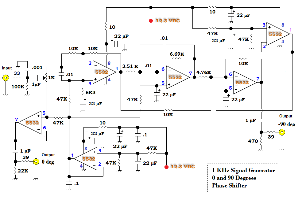
Likely over-designed, I quickly built this on a whimsy to get me going with all-pass filter design. In most all-pass filter work, you've got to design it — and then order and wait for your 1% resistors to arrive. No lag for me: I went from design to test in about 2.5 hours. Previous to the experiments on this page, I'd never even thought about all-pass networks — now I feel excited to learn about and work with them.

Above — Assessment of my narrow band phase shifter. I got pretty close to the design phase error by sorting through my 5% resistors with an ohmmeter and choosing time constant Rs as close as possible to those specified in the schematic. I might order some nearest standard value 1% Rs and see if I can get under 0.1% phase accuracy @ 1 KHz.
Now, along with boosted confidence, I've got something to connect to my AF signal generator for simple assessment of the wide band all-pass networks I build.


The R-C time constant gets fairly critical if you want the maximum possible opposite side band suppression, so buying 1% parts ranks as important.
I won't repeat it, but getting the phase shifter bandwidth as wide ( & flat) as possible; plus comparing various bandwidth all-pass designs with an antenna + speaker attached = key learnings. Rick's filter presented as Figure 9.56 in EMRFD remains a proven, widely reproduced, go-to, all pass network for many. I ordered all the 1% resistors yesterday.
It's also heavy to learn that all opposite side band suppression occurs in the op-amp combiner that immediately follows the all-pass network.

Above — My single resource for AF filter design: Electronic Filter Design Handbook by Arthur B.Williams. [ Reference # 4 ]. That book and Handbook of Filter Synthesis by Анатоль Зверев (1967) serve as the archetype references for analog filter designers. Get them.
Although you can buy software to crunch the math and design wide band, all-pass filters, there is something so organic about looking at tables and grinding out maths with a scientific calculator.
From the Williams book, I designed some filters with various bandwidth from the α constants and method provided.

Ken Kuhn wrote an Excel spreadsheet that plots a graph based on the RC time constants at R1 to 6. He later improved the spread sheet so you can just enter resistor and capacitor values for 1 to 3 all-pass sections. Thus you don't need to calculate the time constant as shown in my work.
Ken granted permission to share the spreadsheet. Click for his file.

Above — The graph of my filter shows too much slop below 2 KHz

Above — The beauty of his spreadsheet = tweaking. I inputted my raw, calculated R1 - 6 values then tweaked R1 to get this lovely transfer function. I will try tweaking with 1% resistor values next.
2 weeks ago I didn't know anything about all-pass filters, now I'm able to at least mathematically design them and more importantly, understand a little about them.
The Table 1 α1 - 6 constants will pretty much work at any reasonably wide bandwidth where you want to get a +/- 0.1 % phase error. You must use 6 total op-amp sections like the all-pass filter template shows.
I plan to experiment to learn more about ZIF receiver topics including the Weaver method of processing the I and Q channels. The material published by Matjaž, S53MV about his ZIF receivers plus his other designs serves as great inspiration to me.
My special thanks to Ken Kuhn for writing and sharing his spreadsheet; Rick, Allison and others on the R2Pro/KK7B Designs Yahoo group — and to you for reading my blog.
References
[1] Experimental Methods in RD Design (EMRFD) First published by the ARRL in 2003. Wes Hayward, W7ZOI, Rick Campbell, KK7B and Bob Larkin, W7PUA.
[2] Twisted-Wire Quadrature Hybrid Directional Couplers for QST, January 1978. Reed Fisher, W2CQH.
[3] Free TI Software to design op-amp filters. Click. I used this to design my 1 KHz all-pass filter.
[4] Electronic Filter Design Handbook. Arthur B. Williams. McGraw-Hill 1987.
[5] From Thomas, LA3PNA : Sage wireline. Basically, just 2 twisted pieces of wire in a piece of copper tubing. Some enamel wire in a thin KS brass tube should do the trick in a homebrew version. I believe it could be coiled up if the total length is to long in a given space, the important part should be that the tube is grounded at both ends. Found this note about the length in ADS: The quarter-wavelength frequency is calculated as: F (MHz) = 1850 / L (inches). Click for wonderful instructional sheet with math + photos.